This is an IBM SurePOS 500. The ON/OFF Switch is located either on the bottom right edge of the screen as indicated or, on the lower right hand side of the till under a flap, which also houses the USB Port (Connectors for the Keyboard).
On/Off Switch next to contrast buttons |
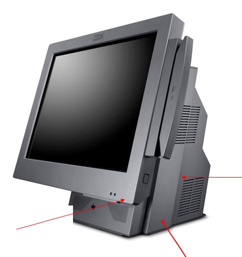 |
On the first version of the till, the On/Off switch is located behind a flap, here. |
The serial number for the till appears on a while insert here. It will start SN ****** |
 |
This is the back of the till with the cover off. The cover is released using the clip at the top then levering back to remove. Please note that the panel on the MKI model is removed differently. Whilst standing in front of the machine, the sides need to be squeezed together and lifted up and away. |
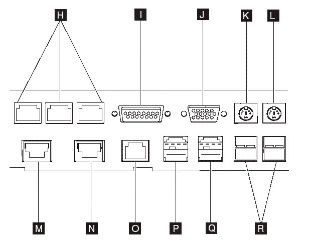
Below is a diagram of the ports and what they connect into.
Reference |
Description |
H |
Serial Ports
|
I |
12v serial Port for the customer display |
J |
Analogue video – Unused |
K |
PS/2 Ports for keyboard/mouse – Unused |
L |
PS/2 Ports for keyboard/mouse – Unused |
M,N |
Cash Drawer Connectors – Plug into port 3A |
O |
Ethernet for connection to the router (yellow cable) |
P |
Powered 24v (Red) For connection to Printer |
Q |
Powered 12v (Green) unused |
R |
USB Ports (4) For Scanner (Keyboard / Memory Pen when needed) |